
Application of Film Capacitor
in Cardiac Defibrillator
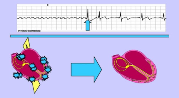
Defibrillation is the only effective way to treat sudden cardiac death
Cardiac defibrillator is currently widely used clinical rescue equipment. It uses pulsed current to act on the heart, implement electric shock therapy, eliminate arrhythmia, and restore the heart to sinus rhythm.
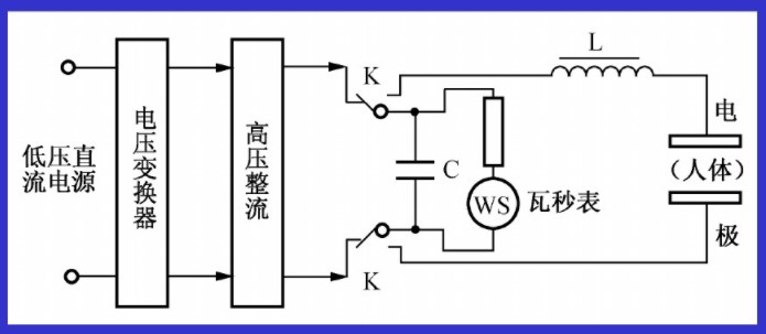
Its working principle mostly adopts RLC damping discharge method, as shown in the figure:

| Typical data | |
| Energy | 100~500J |
| Voltage | 2000~5000VDC |
| Capacitance | 32~200UF |
| Discharge load | 20Ω/50Ω/100Ω |
| Maximum pulse current | 100~1kA |
First charge the energy storage capacitor C to make the capacitor obtain a certain amount of energy. During defibrillation treatment, C, inductance L and human body (load) are connected in series to perform electric shock treatment on the human heart.
● Stored energy
The electric energy charged into the energy storage device before the defibrillation shock. The relationship between the energy stored in the capacitor and the voltage of the capacitor:
E=½cu²
For the application in the defibrillator, the CRE film capacitor has a special customized design, which has higher performance advantages:
Compared with the 10,000 times service life in the market, the special film structure design makes the charging and discharging life times more than 30,000 times
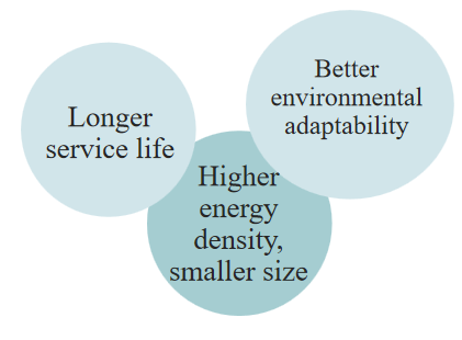
Taking into account the application of uncertain and harsh environment such as outdoor, it adopts special anti-humidity and high temperature resistance design, which has higher reliability
Especially for the small volume design of the external automatic defibrillator (AED) (such as handheld requirements), using high energy density materials, the volume and weight are 50% smaller than the conventional design.
Application 1:
A certain 360J defibrillator model, selecting capacitor model:195UF/2200VDC
SPECIFICATION:
1、RATED VOLTAGE (Un): 2200VDC
2、RATED CAPACITANCE: 200MFD
3、TOLERANCE OF CAPACITANCE: 士5%(J)AT 1KHz, +25℃
4、OPERATION TEMPERATURE: -25℃~+70℃
5、DISSIPATION FACTOR(DF): ≤0.0060 AT 100Hz, +25℃
6、TEST VOLTAGE: TERMINAL TO TERMINAL: 2300VDC/10SEC
7、INSULATION RESISTANCE: AFTER 300 SECONDS ELECTRIFICATION 100VDC, AT +25℃
TERMINAL TO TERMINAL: THE MINIUNM IR SHALL BE≥5000SEC
TERMINAL TO CASE:THE MINIUNM IR SHALL BE≥3000M 2
8、MAX. PUSLE RISE TIME (DV/DT): 5V/ us
9、PEAK CURRENT MAX.: 1000AMPS AT +25℃
10、PULSE DISCHARGE TEST WITH RATE PEAK CURRENT 440A, CHARGE VOLTAGE 2200V 35 SHOTS
11、CASE MATERIAL:FR-PP, UL94 V-o, GRAY-WHITE
12、POTTING MATERIAL: FR-EPOXY, UL94 V-o, GRAY-WHITE
13、LEADS: 1x1 UL 3239 22AWG 150℃, WHITE AND RED
14、TERMINAL: YT396(A)(396-03JR)
15、EXPECTED LIFE 2500 DISCHARGES WTHT A LOAD OF 10 Q
16、DATE CODE: DATE CODE HAS 4 DIGITS AS FOLLOWs:
Take our products and two common manufacturers in the market to do the same test comparison. Under the application conditions of high temperature and humidity, our products have a longer life.
Test conditions:
1. Static test conditions: record capacity, loss, equivalent series resistance. The static parameters are recorded every 10,000 times of charging and discharging. In order to ensure the accuracy of data recording, the capacitor temperature should be as close as possible to the ambient temperature when collecting. The test is carried out at a temperature difference of ≤5 ℃.
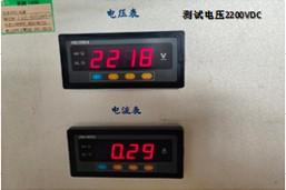
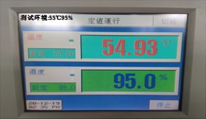
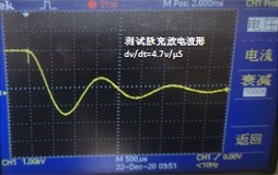
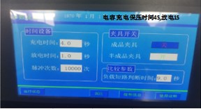
2. Dynamic test conditions: environment 55 ℃ 95%, test terminal voltage 2200V.DC, charge time 4S, discharge time 1S, voltage change rate DV/DT=4.7V/μS, pulse peak current 940A, charge and discharge 20000 times. The test acceleration pulse current is 1.6 times of our company's nominal current (585A).
3. Test process: capacitor static parameters before test.
| NO. | Manufacturer | @100Hz | @1000Hz | ||
| Capacitance(uF) | Loss Tangent | ESR(mΩ) | |||
| 1# | 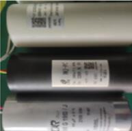 |
FA** | 192.671 | 0.00678 | 55.6 |
| 2# | CRE | 192.452 | 0.00218 | 15.9 | |
| 3# | EI** | 190.821 | 0.00428 | 34.84 | |
● Connect the capacitor to be tested to the test power supply, set the test parameters, and adjust the temperature and humidity test chamber to the specified test environment conditions.
● Start the impulse discharge test on the capacitor according to the set parameters.
● During the test, if the voltage fluctuates abnormally or the capacitor breakdown occurs, the test should be stopped immediately, and static data acquisition and analysis of the capacitor should be performed to confirm whether the test is necessary to continue.
| Charging and discharging times | 1#FA** | |||
| C(uF)@100Hz | tgδ@100Hz | ESR(mΩ)) | Note | |
| Initial value | 192.671 | 0.00678 | 55.6 | After 492 times of test, capacitor terminal voltage dropped to 1720VDC, capacitance decreased by 8.17%. It is not suitable to continue the test. |
| 492 times | 176.932 | 0.00584 | 51.3 | |
| / | Stop the test | |||
| Rate of change | -8.17% | Decline | -7.73% | |
| Charging and discharging times | 2#CRE | |||||
| C(uF)@100Hz | tgδ@100Hz | ESR(mΩ)) | Note | |||
| Initial value | 192.452 | 0.00218 | 15.9 | The capacitance decreased by 0.72% for 1W times and 2.15% for 2W times of test. No obvious abnormality of capacitor. Test continued. | ||
| 10000 veces | 191.07 | 0.0019 | 14.86 | |||
| 20000 veces | 188.315 | 0.0017 | 14.22 | |||
| 30000 veces | In ongoing test | |||||
| Rate of change | -0.72% | -2.15% | Decline | -6.54% | -10.57% | |
| Charging and discharging times | 3#EI** | |||
| C(uF)@100Hz | tgδ@100Hz | ESR(mΩ)) | Note | |
| Initial value | 192.452 | 0.00218 | 15.9 | After 257 times of test, the capacitance decreased by 1.89%. The capacitor terminal voltage dropped to zero. The capacitor presents a short circuit state, and the test stopped. |
| 257 veces | 191.07 | 0.0019 | 14.86 | |
| / | Stop test | |||
| Rate of change | -1.89% | The tangent of loss Angle is abnormal | Anormal | |
Application 2:
This program is specially designed for the small size of a 180J handheld external automatic defibrillator (AED), the specification is 100UF/2000VDC.
| Size(mm) | Volume(m³) | |
| Conventional scheme | Φ50*115 | 225.8 |
| Miniaturization scheme | Φ35*120 | 115 |
| After the miniaturized design, the volume and weight are 50% smaller than the conventional design. | ||
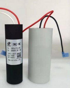
Comparison of miniaturized design and original size
By comparing the parameters of the product after 5000 times of impulsive discharge, the capacity attenuation is only less than 3%, which can guarantee its long-term service life.
| Capacitance before test | Capacitance after test | Loss before test | Loss after test | |
| 1 | 95.38 | 93.80 | 0.00236 | 0.00243 |
| 2 | 95.56 | 94.21 | 0.00241 | 0.00238 |
| 3 | 96.58 | 95.33 | 0.00239 | 0.00243 |
| 4 | 95.53 | 92.81 | 0.00244 | 0.00241 |
Download Files