
This week we’re going to analyze the use of film capacitors instead of electrolytic capacitors in DC-link capacitors. This article will be divided into two parts.
With the development of new energy industry, variable current technology is commonly used accordingly, and DC-Link capacitors are particularly important as one of the key devices for selection. The DC-Link capacitors in DC filters generally require large capacity, high current processing and high voltage, etc. By comparing the characteristics of film capacitors and electrolytic capacitors and analyzing the related applications, this paper concludes that in circuit designs requiring high operating voltage, high ripple current (Irms), over-voltage requirements, voltage reversal, high inrush current (dV/dt) and long life. With the development of metallized vapor deposition technology and film capacitor technology, film capacitors will become a trend for designer to replace electrolytic capacitors in terms of performance and price in the future.
With the introduction of new energy related policies and the development of new energy industry in various countries, the development of related industries in this field has brought new opportunities. And capacitors, as an essential upstream related product industry, have also gained new development opportunities. In new energy and new energy vehicles, capacitors are key components in energy control, power management, power inverter and DC-AC conversion systems that determine the life of the converter. However, in the inverter, DC power is used as the input power source, which is connected to the inverter through a DC bus, which is called DC-Link or DC support. Since the inverter receives high RMS and peak pulse currents from the DC-Link, it generates high pulse voltage on the DC-Link, ,making it difficult for the inverter to withstand. Therefore, the DC-Link capacitor is needed to absorb the high pulse current from the DC-Link and prevent the high pulse voltage fluctuation of the inverter is within the acceptable range; on the other hand, it also prevents the inverters from being affected by the voltage overshoot and transient over-voltage on the DC-Link.
The schematic diagram of the use of DC-Link capacitors in new energy ( including wind power generation and photovoltaic power generation) and new energy vehicle motor drive systems are shown in Figures 1 and 2.
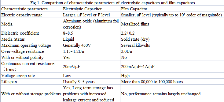
Figure 1 shows the wind power converter circuit topology, where C1 is DC-Link (generally integrated to the module ), C2 is IGBT absorption, C3 is LC filtering (net side), and C4 rotor side DV/DT filtering. Figure 2 shows the PV power converter circuit technology, where C1 is DC filtering, C2 is EMI filtering, C4 is DC-Link, C6 is LC filtering (grid side), C3 is DC filtering, and C5 is IPM/IGBT absorption. Figure 3 shows the main motor drive system in the new energy vehicle system, where C3 is DC-Link and C4 is IGBT absorption capacitor.
In the above mentioned new energy applications, DC-Link capacitors, as a key device, are required for high reliability and long life in wind power generation systems, photovoltaic power generation systems and new energy vehicle systems, so their selection is particularly important. The following is a comparison of the characteristics of film capacitors and electrolytic capacitors and their analysis in DC-Link capacitor application.
1.Feature comparison
1.1 Film capacitors
The principle of film metallization technology is first introduced: a sufficiently thin layer of metal is vaporized on the surface of the thin film media. In the presence of a defect in the medium, the layer is able to evaporate and thus isolate the defective spot for protection, a phenomenon known as self-healing.
Figure 4 shows the principle of metallization coating, where the thin film media is pretreated (corona of otherwise) before vaporization so that metal molecules can adhere to it. The metal is evaporated by dissolving at high temperature under vacuum (1400℃ to 1600℃ for aluminum and 400℃ to 600℃ for zinc), and the metal vapor condensed on the surface of the film when it meets the cooled film (film cooling temperature -25℃ to -35℃), thus forming a metal coating. The development of metallization technology has improve the dielectric strength of the film dielectric per unit thickness, and the design of capacitor for pulse or discharge application of dry technology can reach 500V/µm, and and the design of capacitor for DC filter application can reach 250V/µm. DC-Link capacitor belongs to the latter, and according to IEC61071 for power electronics application capacitor can withstand more severe voltage shock, and can reach 2 times the rated voltage.
Therefore, the user only needs to consider the rated operating voltage required for their design. Metallized film capacitors have a low ESR, which allows them to withstand larger ripple currents; the lower ESL meets the low inductance design requirements of inverters and reduces the oscillation effect at switching frequencies.
The quality of the film dielectric, the quality of the metallization coating, the capacitor design and the manufacturing process determine the self-healing characteristics of the metallized capacitors. The film dielectric used for DC-Link capacitors manufactured is mainly OPP film.
The content of chapter 1.2 will be published in next week’s article.
Post time: Mar-22-2022