
This week we continue with last week’s article.
1.2 Electrolytic capacitors
The dielectric used in electrolytic capacitors is aluminum oxide formed by corrosion of aluminum, with a dielectric constant of 8 to 8.5 and a working dielectric strength of about 0.07V/A (1µm=10000A). However, it is not possible to achieve such a thickness. The thickness of aluminum layer reduces the capacity factor (specific capacitance) of electrolytic capacitors because the aluminum foil has to be etched to form an aluminum oxide film to obtain good energy storage characteristics, and the surface will form many uneven surfaces. On the other hand, the resistivity of electrolyte is 150Ωcm for low voltage and 5kΩcm for high voltage (500V). The higher resistivity of the electrolyte limits the RMS current that the electrolytic capacitor can withstand, typically to 20mA/µF.
For these reasons electrolytic capacitors are designed for maximum voltage of 450V typical (some individual manufacturers design for 600V). Therefore, in order to obtain higher voltages it’s necessary to achieve them by connecting capacitors in series. However, because of the difference in insulation resistance of each electrolytic capacitor, a resistor must be connected to each capacitor in order to balance the voltage of each series connected capacitor. In addition, electrolytic capacitors are polarized devices, and when the applied reverse voltage exceeds 1.5 times Un, an electrochemic reaction occurs. When the applied reverse voltage is long enough, the capacitor will spill out. In order to avoid this phenomenon, a diode should be connected next to each capacitor when it is used. Besides, the voltage surge resistance of electrolytic capacitors is generally 1.15 times Un, and the good ones can reach 1.2 times Un. So the designers should consider not only the steady-state working voltage but also the surge voltage when using them. In summary, the following comparison table between film capacitors and electrolytic capacitors can be drawn, see Fig.1.

2. Application Analysis
DC-Link capacitors as filters require high current and high capacity designs. An example is the main motor drive system of a new energy vehicle as mentioned in Fig.3. In this application the capacitor plays a decoupling role and the circuit features a high operating current. The film DC-Link capacitor has the advantage of being able to withstand large operating currents (Irms). Take 50~60kW new energy vehicle parameters as an example, the parameters are as follows: operating voltage 330 Vdc, ripple voltage 10Vrms, ripple current 150Arms@10KHz.
Then the minimum electrical capacity is calculated as:
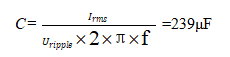
This is easy for implement for film capacitor design. Assuming that electrolytic capacitors are used, if 20mA/μF is considered, the minimum capacitance of the electrolytic capacitors is calculated to meet the above parameters as follows:
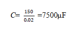
This requires multiple electrolytic capacitors in parallel connected to obtain this capacitance.
In over-voltage applications, such as light rail, electric bus, subway, etc. Considering that these powers are connected to the locomotive pantograph through the pantograph, the contact between the pantograph and the pantograph is intermittent during the transportation travel. When the two are not in contact, the power supply is supported by the DC-L ink capacitor, and when the contact is restored, the over-voltage is generated. The worst case is a complete discharge by the DC-Link capacitor when disconnected, where the discharge voltage is equal to the pantograph voltage, and when contact is restored, the resulting over-voltage is almost two times the rated operating Un. For film capacitors the DC-Link capacitor can be handled without additional consideration. If electrolytic capacitors are used, the over-voltage is 1.2Un. Take Shanghai metro as an example. Un=1500Vdc, for electrolytic capacitor to consider the voltage is: 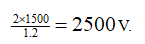
Then the six 450V capacitors are to be connected in series. If film capacitor design is used in 600Vdc to 2000Vdc or even 3000Vdc is easily achieved. In addition, the energy in the case of fully discharging the capacitor forms a short circuit discharge between the two electrodes, generating a large inrush current through the DC-Link capacitor, which is usually different for electrolytic capacitors to meet the requirements.
In addition, compared to electrolytic capacitors DC-Link film capacitors can be designed to achieve very low ESR (typically below 10mΩ, and even lower <1mΩ) and self-inductance LS (typically below 100nH, and in some cases below 10 or 20nH). This allows the DC-Link film capacitor to be installed directly into the IGBT module when applied, allowing the bus bar to be integrated into the DC-Link film capacitor, thus eliminating the need for a dedicated IGBT absorber capacitor when using film capacitors, saving the designer a significant amount of money. Fig.2. and 3 show the technical specifications of some of C3A and C3B products.
3. Conclusion
In the early days, DC-Link capacitors were mostly electrolytic capacitors due to cost and size considerations.
However, electrolytic capacitors are affected by voltage and current withstand capability (much higher ESR compared to film capacitors), so it is necessary to connect several electrolytic capacitors in series and parallel in order to obtain large capacity and meet the requirements of high voltage use. In addition, considering the volatilization of electrolyte material, it should be replaced regularly. New energy applications generally require a product life of 15 years, so it must be replaced 2 to 3 times during this period. Therefore, there is a considerable cost and inconvenience in the after-sales service of the whole machine. With the development of metallization coating technology and film capacitor technology, it has been possible to produce high-capacity DC filter capacitors with voltage from 450V to 1200V or even higher with ultra-thin OPP film(the thinnest 2.7µm, even 2.4µm) using safety film vaporization technology. On the other hand, the integration of DC-Link capacitors with the bus bar makes the inverter module design more compact and greatly reduces the stray inductance of the circuit to optimize the circuit.
Post time: Mar-29-2022