
This week, we’ll have an introduction to the metallized film capacitor winding technics. This article introduces the relevant processes involved in film capacitor winding equipment, and gives a detailed description of the key technologies involved, such as tension control technology, winding control technology, demetalization technology, and heat sealing technology.
Film capacitors have been used more and more widely for their excellent characteristics. Capacitors are widely used as basic electronic components in electronic industries such as household appliances, monitors, lighting appliances, communication products, power supplies, instruments, meters and other electronic devices. Commonly used capacitors are paper dielectric capacitors, ceramic capacitors, electrolytic capacitors, etc. Film capacitors are gradually occupying a larger and larger market because of their excellent characteristics, such as small size, light weight. Stable capacitance, high insulation impedance, wide frequency response and small dielectric loss.
Film capacitors are roughly divided into: laminated type and wound type according to the different ways of core processing. The film capacitor winding process introduced here is mainly for winding conventional capacitors, i.e. capacitor cores made of metal foil, metalized film, plastic film and other materials (general-purpose capacitors, high- voltage capacitors, safety capacitors, etc.), which are widely used in timing, oscillation and filter circuits, high frequency, high pulse and high current occasions, screen monitors and color TV line reverse circuit, power supply cross-line noise reduction circuit, anti-interference occasions, etc.
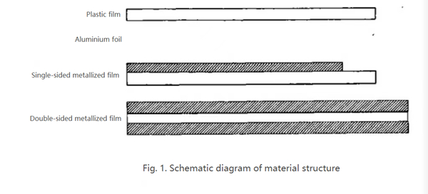
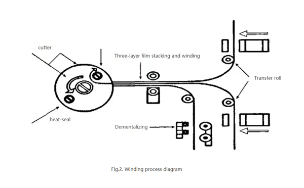
Next, we will introduce the winding process in detail. The technics of capacitor winding is by winding metal film, metal foil and plastic film on the core, and setting different winding turns according to the capacitor core capacity. When the number of winding turns is reached, the material is cut off, and finally the break is sealed to complete the winding of the capacitor core. The schematic diagram of the material structure is shown in Fig. 1. the schematic diagram of winding process is shown in Fig. 2.
There’re many factors affecting the capacitance performance during the winding process, such as the flatness of the material hanging tray, the smoothness of the surface of the transition roller, the tension of the winding material, the demetalliaztion effect of the film material, the sealing effect at the break, the way of winding material stacking, etc. All these will have a big impact on the performance testing of the final capacitor core.
The common way to seal the outer end of the capacitor core is by heat sealing with a soldering iron. By heating the tip of the iron (temperature depends on the process of different products). In the case of low-speed rotation of the rolled core, the tip of the soldering iron is brought into contact with the outer sealing film of the capacitor core and sealed by hot stamping. The quality of the seal directly affects the appearance of the core.
The plastic film at the sealing end is often obtained in two ways: one is to add a layer of plastic film to the winding, which increases the thickness of the capacitor dielectric layer and also increases the diameter of the capacitor core. The other way is to remove the metal film coating at the end of the winding to obtain the plastic film with the metal coating removed, which can reduce the diameter of the core with the same capacity of the capacitor core.
Post time: Mar-01-2022