
Every time an IGBT turns off, something violent happens in a very small window of time.
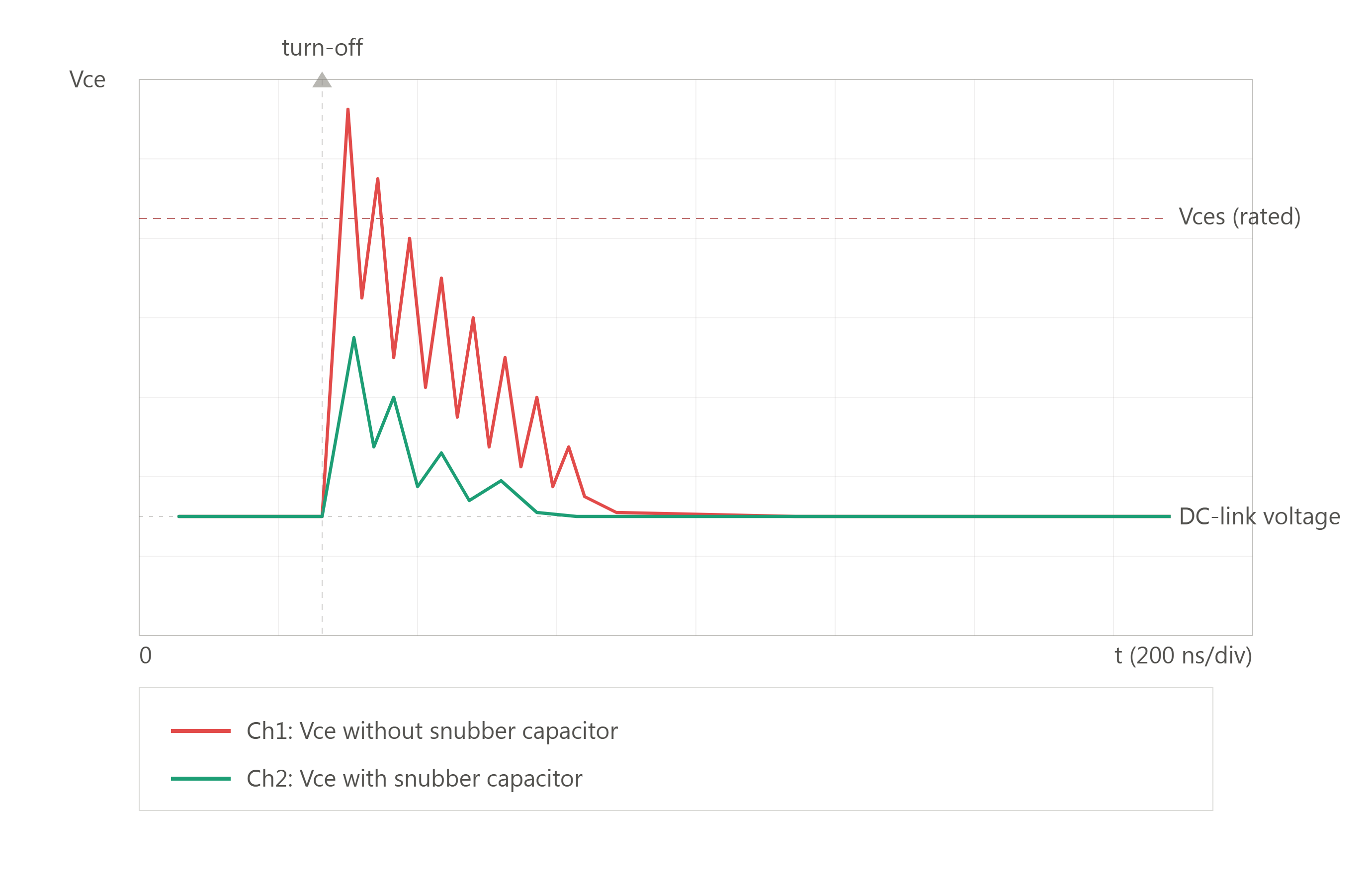
Voltage waveform comparison showing IGBT turn-off spike with and without a CRE snubber capacitor
The current flowing through the device gets interrupted. The energy stored in the circuit’s stray inductance has nowhere to go. It releases as a voltage spike. If nothing absorbs that spike, it can exceed the IGBT’s rated voltage and damage the device.
This is the exact problem a snubber capacitor is built to solve. And it’s worth understanding properly, because the difference between a good snubber capacitor and a mediocre one shows up as device failures months or years down the line, not on day one.
The Job of a Snubber Capacitor
A snubber capacitor sits across the switching device and gives that released energy somewhere safe to go.
When the IGBT switches off, the capacitor absorbs the transient current and limits how fast the voltage rises (dv/dt) across the device. That single function does three things at once: it suppresses voltage spikes, it reduces switching losses, and it smooths out the abrupt current and voltage changes that stress the rest of the circuit.
For this to work well, two electrical properties matter more than anything else: low equivalent series resistance (ESR) and low equivalent series inductance (ESL). High ESR or ESL slows the capacitor’s response and limits how effectively it can clamp a fast transient. This is also why metallized polypropylene film is the material of choice for most snubber applications. It combines low ESR/ESL with a self-healing dielectric, so the capacitor keeps performing reliably even after repeated voltage stress.
Inside the SMJ-P : CRE’s Plastic Box IGBT Snubber Capacitor
CRE’s SMJ-P is a plastic-box snubber capacitor purpose-built for IGBT protection, with tin-plated copper insert leads for straightforward installation directly onto the IGBT module.
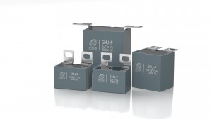
CRE SMJ-P plastic box IGBT snubber capacitor with tin-plated copper leads
Key technical parameters:
|
Parameter |
Specification |
| Capacitance range | 0.1μF to 5.6μF |
| Rated voltage | 700V DC to 3000V DC |
| Capacitance tolerance | ±5% (J) / ±10% (K) |
| Operating temperature | -40°C to +85°C (category), up to +105°C max hotspot |
| Withstand voltage | 1.5x rated voltage DC, 10s |
| Dissipation factor | tgδ < 0.0005 (C ≤ 1μF) / tgδ < 0.001 (C > 1μF), at 10kHz |
| Insulation resistance | Rs ≥ 30,000 MΩ (C ≤ 0.33μF) / Rs×C ≥ 10,000s (C > 0.33μF), at 20°C, 100V DC, 60s |
| Flame retardation | UL94V-0 |
| Life expectancy | 100,000h at rated voltage, hotspot ≤85°C |
| Reference standards | IEC 61071, GB/T 17702 |
The construction itself is built around the same logic as the electrical performance. The plastic case is sealed with resin, which protects the winding from moisture and mechanical stress. Both axial and radial lead configurations are available, so the same capacitor family can fit different module layouts without a custom redesign every time.
A Detail Most Articles Skip: Lead Geometry Matters as Much as Capacitance
Most snubber capacitor content stops at “use polypropylene film, it self-heals.” That’s true, but it’s only half the engineering story, and it’s the half that doesn’t actually decide whether a given part works in a given circuit.
The other half is loop inductance. The capacitance value alone doesn’t guarantee a low voltage spike if the capacitor’s self-inductance remains high, because the remaining inductance in the loop between the terminals and the internal connections is itself responsible for generating a voltage spike or transient. In other words, a high-capacitance part with long, thin leads can underperform a smaller part with short, wide terminals.
Diagram comparing loop inductance between long-lead and direct-mount snubber capacitor terminals
This is also why the mounting method matters more than it looks on a datasheet. Capacitors with wide, flat terminals that can be screwed directly onto the IGBT module achieve lower self-inductance than parts connected through long lead wires. SMJ-P’s tin-plated copper insert leads and choice of axial or radial configuration exist for exactly this reason: to keep the connection path short and let the rated capacitance actually deliver the dv/dt protection it’s specified for.
The self-healing property still matters, separately. A metallized polypropylene film that experiences a localized dielectric breakdown isolates that fault in microseconds, instead of failing outright, which is why film remains the standard dielectric for this application over ceramic or electrolytic alternatives. But self-healing and low loop inductance are two different engineering problems, and a snubber capacitor has to get both right.
SMJ-P Within CRE’s Broader Snubber Capacitor Range
The SMJ-P plastic-box format is one of several lead and case configurations CRE offers for IGBT and GTO snubber protection. Depending on mounting space, lead orientation, and thermal requirements, CRE also produces axial-lead and Mylar-tape variants built on the same metallized polypropylene film technology and engineered to the same ESR/ESL performance standards. This means a design team can move between formats as a layout evolves, without re-qualifying the underlying dielectric system from scratch.
How Engineers Verify a Snubber Capacitor Choice
Capacitance and voltage rating on a datasheet aren’t enough to confirm a snubber capacitor will work in a given circuit. The standard verification method, documented by SEMIKRON in its IGBT application notes, is to measure the actual collector-emitter voltage waveform at turn-off, with and without the snubber capacitor in place, and confirm the peak stays within the IGBT’s rated blocking voltage under worst-case conditions. After turn-off, current commutates into the snubber capacitor, producing a current peak at the switching instant, followed by a damped oscillation between the snubber capacitor and the DC-link, with the oscillation frequency set by the bus bar’s parasitic inductance and the snubber capacitor’s value.
This same emphasis on lead geometry and direct-mount terminal hardware as a primary design variable, rather than an afterthought, is echoed in widely circulated power electronics design literature, including Rudy Severns’ snubber design reference published by Cornell Dubilier. The underlying physics is also formalized in IEC 61071, the international standard governing capacitors for power electronics, which SMJ-P is designed to meet. The point across all of these sources is consistent: the goal isn’t just a capacitance value on a spec sheet, it’s a measured, repeatable reduction in peak voltage at turn-off.
Where SMJ-P Capacitors Get Used
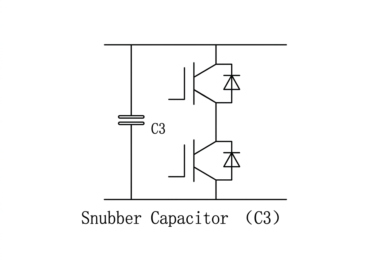
Half-bridge IGBT circuit diagram with snubber capacitor C3 connected across the DC bus rails.
Snubber capacitors aren’t a niche component. They show up wherever a power switching device needs protection from its own switching action:
• Inverters and motor drives, where IGBTs switch continuously and need consistent dv/dt protection
• Electric vehicle power electronics, where switching efficiency and component longevity directly affect range and reliability
• Renewable energy systems, including solar inverters, where voltage spike suppression protects high-power switching devices over decades of operation
• Rectifiers, SVCs, and locomotive power supplies, where high pulse currents and demanding duty cycles make ESR and ESL performance especially critical
The common thread across all of these applications is the same: switching devices generate transients, and something has to absorb them cleanly, cycle after cycle, for the lifetime of the system.
Why Material and Manufacturing Choices Compound Over Time
A snubber capacitor’s job looks simple on a datasheet. In practice, performance is decided by details that don’t show up until the system has been running for years: how consistently the dielectric self-heals after stress, how tightly ESR and ESL are controlled across a production batch, and whether the insulation resistance holds up across the full temperature range rather than just at room temperature.
This is why CRE’s SMJ-P ties its 100,000-hour life expectancy rating to a specific hotspot temperature condition (≤85°C), rather than stating it as a generic number, and why insulation resistance is specified separately by capacitance range rather than as a single blanket figure. These are the kinds of specifications that matter to an engineer validating a design, not just a marketing claim.
FAQ: IGBT Snubber Capacitor Selection
Q1:What is an IGBT snubber capacitor used for?
An IGBT snubber capacitor suppresses voltage spikes generated when an IGBT switches off, protecting the device from exceeding its rated blocking voltage. CRE’s SMJ-P metallized polypropylene film capacitor is engineered for this purpose, with a rated voltage range of 700V DC to 3000V DC.
Q2:How do I choose the right snubber capacitor manufacturer?
Look for a manufacturer that offers low-ESR/ESL film capacitors, recognized certifications (IEC 61071, UL94V-0), and custom capacitance or voltage options. CRE is a film capacitor manufacturer supplying DC-Link, IGBT snubber, and EMC-filter capacitors for power electronics, renewable energy, and rail transit applications, with both axial and radial lead configurations available.
Q3:What makes a polypropylene film capacitor better than other snubber capacitor types?
Metallized polypropylene film offers low ESR/ESL, self-healing dielectric properties, and stable performance over a wide temperature range, making it the standard dielectric for snubber applications compared with electrolytic or ceramic alternatives. CRE’s SMJ-P operates from -40°C to +85°C with a rated 100,000-hour life expectancy.
Full technical documentation for the SMJ-P is available here: https://www.crecapacitors.com/IGBT-GTO-Snubber-Capacitors-pl47325307.html
References:
1. CRE NEW ENERGY, “Plastic Box IGBT Snubber Capacitor SMJ-P,” Product Datasheet. (https://www.crecapacitors.com/IGBT-GTO-Snubber-Capacitors-pl47325307.html)
2. Semikron Danfoss, “IGBT Peak Voltage Measurement and Snubber Capacitor Specification, “Application Note AN 07-006.
(https://assets.danfoss.com/documents/latest/444044/AB501644922487en-000201.pdf)
3. Severns, Rudy. “Design of Snubbers for Power Circuits.” Cornell Dubilier Application Note. (https://www.cde.com/resources/technical-papers/design.pdf)
Technical specifications reflect published data at the time of writing. Readers should confirm current ratings against the manufacturer’s latest datasheet before final design use.
Post time: Jul-03-2026