2018 New Style Customized Capacitor Bank - Advanced embedded PCB capacitor designed for high power system – CRE
2018 New Style Customized Capacitor Bank - Advanced embedded PCB capacitor designed for high power system – CRE Detail:
Technical data
|
Operating temperature range |
Max.Operating temperature.,Top,max: +105℃Upper category temperature: +85℃Lower category temperature: -40℃ |
|
capacitance range |
3~50μF |
|
Rated voltage |
200V.AC~450V.AC |
|
Cap.tol |
±5%(J) ;±10%(K) |
|
Withstand voltage |
2Un DC/10S |
|
Dissipation factor |
tgδ≤0.0015f=1KHz |
|
Insulation resistance |
RS*C≥5000S(at20℃ 100V.DC60S) |
|
Flame retardation |
UL94V-0 |
|
Life expectancy |
100000h(Un; Θhotspot≤70 °C) |
|
Reference standard |
IEC61071; |
|
Operating temperature range |
Max.Operating temperature.,Top,max: +105℃Upper category temperature: +85℃Lower category temperature: -40℃ |
|
capacitance range |
3~50μF |
|
Rated voltage |
200V.AC~450V.AC |
|
Cap.tol |
±5%(J) ;±10%(K) |
|
Withstand voltage |
2Un DC/10S |
|
Dissipation factor |
tgδ≤0.0015f=1KHz |
|
Insulation resistance |
RS*C≥5000S(at20℃ 100V.DC60S) |
|
Flame retardation |
UL94V-0 |
|
Life expectancy |
100000h(Un; Θhotspot≤70 °C) |
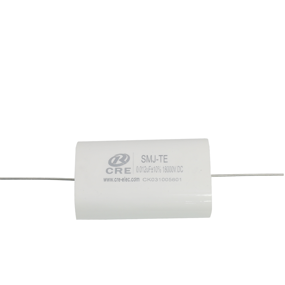
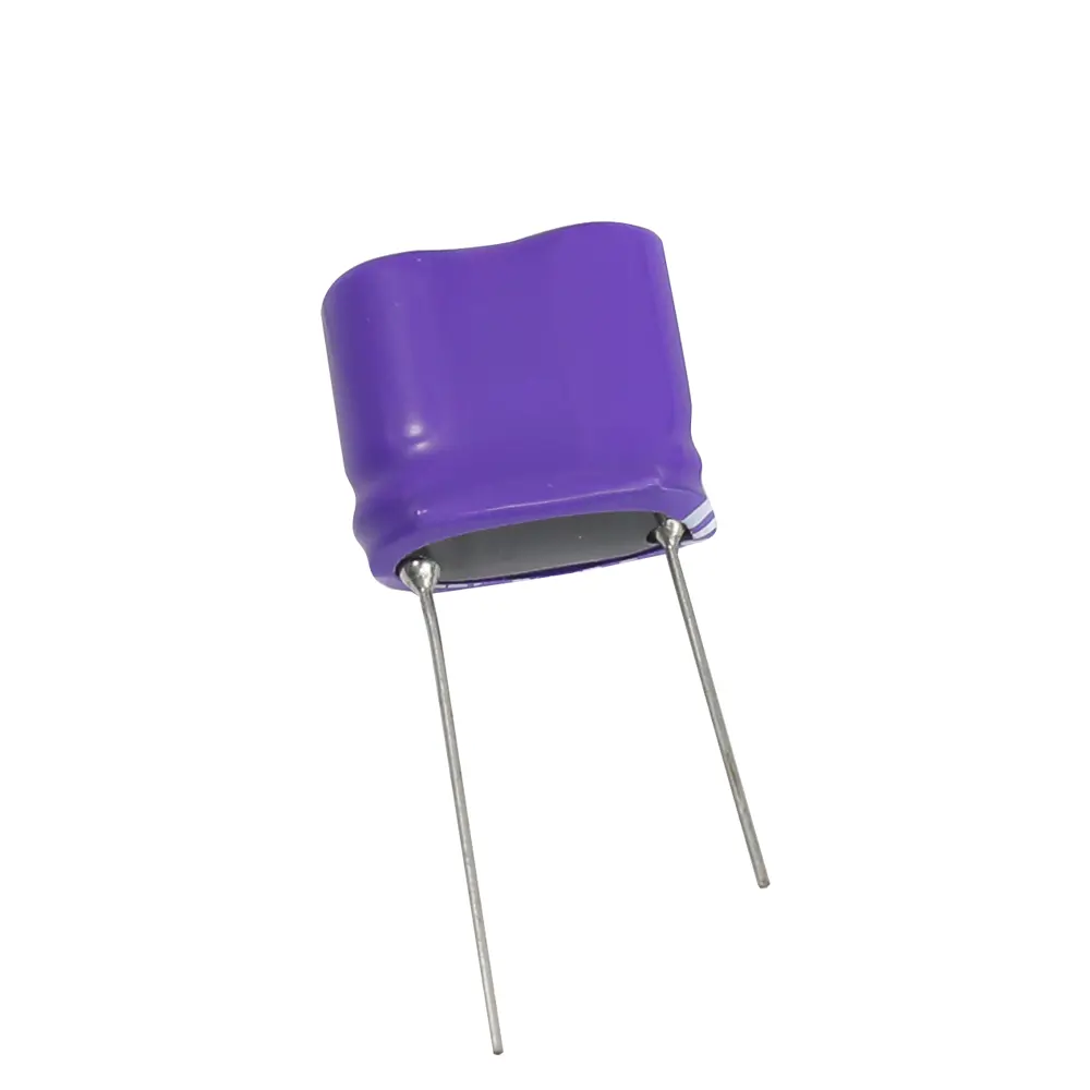
Feature
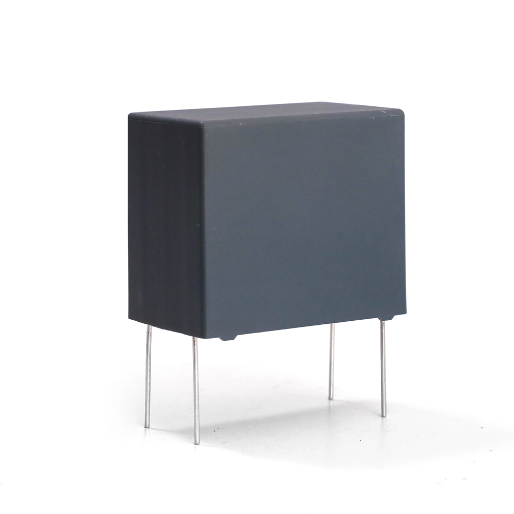
1. dry film construction;
2. leads with Tinned copper wire;small size.easy installation;
3. low ESL and ESR;
4. High pulse Current.
Application
1. Widely used in DC-Link circuit for filtering energy storage;
2. Can replace electrolytic capacitors, better performance and longer life.
3. Pv inverter, wind power converter; all kinds of frequency converter and inverter power supply;
Pure electric and hybrid cars; Charging pile, UPS, Etc.
Outline drawing
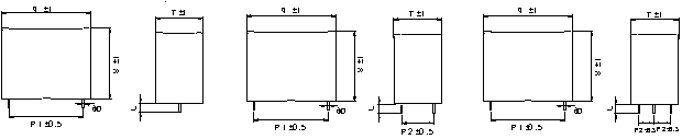
| (mm) | ||||||||||
| Cn(μF) | L(±1) | T(±1) | H(±1) | φd | P1 | P2 | ESR @10KHz (mΩ) | dv/dt (V/μS) | Ipk(A) | Irms @40℃ @10KHz (A) |
| 20 | 42.5 | 30 | 45 | 1.2 | 37.5 | 2.3 | 30 | 600 | 12 | |
| 20 | 42.5 | 30 | 45 | 1.2 | 37.5 | 20.3 | 1.8 | 30 | 600 | 22 |
| 25 | 57.5 | 30 | 45 | 1.2 | 52.5 | 3.8 | 17 | 425 | 12 | |
| 25 | 57.5 | 30 | 45 | 1.2 | 52.5 | 20.3 | 3.2 | 17 | 425 | 22 |
| 30 | 57.5 | 30 | 45 | 1.2 | 52.5 | 3.5 | 17 | 510 | 12 | |
| 30 | 57.5 | 30 | 45 | 1.2 | 52.5 | 20.3 | 2.9 | 17 | 510 | 22 |
| 30 | 57.5 | 30 | 45 | 1.2 | 52.5 | 10.2 | 2.8 | 17 | 510 | 25 |
| 33 | 57.5 | 35 | 50 | 1.2 | 52.5 | 3.3 | 17 | 561 | 12 | |
| 33 | 57.5 | 35 | 50 | 1.2 | 52.5 | 20.3 | 2.7 | 17 | 561 | 22 |
| 33 | 57.5 | 35 | 50 | 1.2 | 52.5 | 10.2 | 2.6 | 17 | 561 | 28 |
| 35 | 57.5 | 35 | 50 | 1.2 | 52.5 | 3.2 | 17 | 595 | 12 | |
| 35 | 57.5 | 35 | 50 | 1.2 | 52.5 | 20.3 | 2.6 | 17 | 595 | 22 |
| 35 | 57.5 | 35 | 50 | 1.2 | 52.5 | 10.2 | 2.5 | 17 | 595 | 30 |
| 40 | 57.5 | 35 | 50 | 1.2 | 52.5 | 3 | 17 | 680 | 12 | |
| 40 | 57.5 | 35 | 50 | 1.2 | 52.5 | 20.3 | 2.4 | 17 | 680 | 22 |
| 40 | 57.5 | 35 | 50 | 1.2 | 52.5 | 10.2 | 2.3 | 17 | 680 | 30 |
| 45 | 57.5 | 38 | 54 | 1.0 | 52.5 | 2.8 | 17 | 765 | 12 | |
| 45 | 57.5 | 38 | 54 | 1.0 | 52.5 | 20.3 | 2.3 | 17 | 765 | 22 |
| 45 | 57.5 | 38 | 54 | 1.0 | 52.5 | 10.2 | 2.2 | 17 | 765 | 32 |
| 50 | 57.5 | 42.5 | 56 | 1.2 | 52.5 | 2.7 | 17 | 850 | 12 | |
| 50 | 57.5 | 42.5 | 56 | 1.2 | 52.5 | 20.3 | 2.2 | 17 | 850 | 22 |
| 50 | 57.5 | 42.5 | 56 | 1.2 | 52.5 | 10.2 | 2.1 | 17 | 850 | 32 |
| Voltage | Un 400V.DC,Urms250Vac;Us800V | |||||||||
| (mm) | ||||||||||
| Cn(μF) | L(±1) | T(±1) | H(±1) | φd | P1 | P2 | ESR(mΩ) | dv/dt(V/μS) | Ipk(A) | Irms |
| 10 | 42.5 | 33.5 | 35.5 | 1.2 | 37.5 | 2.6 | 40 | 400 | 12 | |
| 10 | 42.5 | 33.5 | 35.5 | 1.2 | 37.5 | 20.3 | 2 | 40 | 400 | 23 |
| 15 | 42.5 | 30 | 45 | 1.2 | 37.5 | 2.3 | 40 | 600 | 28 | |
| 15 | 42.5 | 30 | 45 | 1.2 | 37.5 | 20.3 | 1.8 | 40 | 600 | 28 |
| 15 | 42.5 | 30 | 45 | 1.2 | 37.5 | 10.2 | 1.7 | 40 | 600 | 28 |
| 18 | 42.5 | 33 | 45 | 1.2 | 37.5 | 2.2 | 40 | 720 | 15 | |
| 18 | 42.5 | 33 | 45 | 1.2 | 37.5 | 20.3 | 1.7 | 40 | 720 | 15 |
| 18 | 42.5 | 33 | 45 | 1.2 | 37.5 | 10.2 | 1.6 | 40 | 720 | 15 |
| 20 | 57.5 | 30 | 45 | 1.2 | 52.5 | 3.5 | 20 | 400 | 25 | |
| 20 | 57.5 | 30 | 45 | 1.2 | 52.5 | 20.3 | 2.9 | 20 | 400 | 25 |
| 20 | 57.5 | 30 | 45 | 1.2 | 52.5 | 10.2 | 2.8 | 20 | 400 | 25 |
| 25 | 57.5 | 35 | 50 | 1.2 | 52.5 | 3.4 | 20 | 500 | 28 | |
| 25 | 57.5 | 35 | 50 | 1.2 | 52.5 | 20.3 | 2.8 | 20 | 500 | 28 |
| 25 | 57.5 | 35 | 50 | 1.2 | 52.5 | 10.2 | 2.7 | 20 | 500 | 28 |
| 30 | 57.5 | 38 | 54 | 1.2 | 52.5 | 3.2 | 20 | 600 | 25 | |
| 30 | 57.5 | 38 | 54 | 1.2 | 52.5 | 20.3 | 2.7 | 20 | 600 | 25 |
| 30 | 57.5 | 38 | 54 | 1.2 | 52.5 | 10.2 | 2.6 | 20 | 600 | 25 |
| Voltage | Un 600V.DC,Urms330Vac;Us1200V | |||||||||
| (mm) | ||||||||||
| Cn(μF) | L(±1) | T(±1) | H(±1) | φd | P1 | P2 | ESR(mΩ) | dv/dt(V/μS) | Ipk(A) | Irms |
| 5 | 42.5 | 33.5 | 35.5 | 1.2 | 37.5 | 3.1 | 55 | 275 | 12 | |
| 5 | 42.5 | 33.5 | 35.5 | 1.2 | 37.5 | 20.3 | 2.5 | 55 | 275 | 20 |
| 6.8 | 42.5 | 30 | 45 | 1.2 | 37.5 | 2.8 | 55 | 374 | 12 | |
| 6.8 | 42.5 | 30 | 45 | 1.2 | 37.5 | 20.3 | 2.2 | 55 | 374 | 22 |
| 9 | 42.5 | 30 | 45 | 1.2 | 37.5 | 2.6 | 55 | 495 | 12 | |
| 9 | 42.5 | 30 | 45 | 1.2 | 37.5 | 20.3 | 2.2 | 55 | 495 | 22 |
| 9 | 42.5 | 30 | 45 | 1.2 | 37.5 | 10.2 | 1.9 | 55 | 495 | 28 |
| 10 | 57.5 | 30 | 45 | 1.2 | 52.5 | 4.2 | 30 | 300 | 22 | |
| 10 | 57.5 | 30 | 45 | 1.2 | 52.5 | 20.3 | 3.7 | 30 | 300 | 25 |
| 15 | 57.5 | 35 | 50 | 1.2 | 52.5 | 3.6 | 30 | 450 | 12 | |
| 15 | 57.5 | 35 | 50 | 1.2 | 52.5 | 20.3 | 2.8 | 30 | 450 | 20 |
| 15 | 57.5 | 35 | 50 | 1.2 | 52.5 | 10.2 | 2.7 | 30 | 450 | 28 |
| Voltage | Un 700V.DC,Urms400Vac;Us1400V | |||||||||
| (mm) | ||||||||||
| Cn(μF) | L(±1) | T(±1) | H(±1) | φd | P1 | P2 | ESR(mΩ) | dv/dt(V/μS) | Ipk(A) | Irms |
| 4.7 | 42.5 | 30 | 45 | 1.2 | 37.5 | 3 | 70 | 329 | 12 | |
| 4.7 | 42.5 | 30 | 45 | 1.2 | 37.5 | 20.3 | 2.4 | 70 | 329 | 22 |
| 5 | 42.5 | 30 | 45 | 1.2 | 37.5 | 2.9 | 70 | 350 | 12 | |
| 5 | 42.5 | 30 | 45 | 1.2 | 37.5 | 20.3 | 2.3 | 70 | 350 | 22 |
| 6 | 42.5 | 33 | 45 | 1.2 | 37.5 | 2.8 | 70 | 420 | 12 | |
| 6 | 42.5 | 33 | 45 | 1.2 | 37.5 | 20.3 | 2.2 | 70 | 420 | 22 |
| 8 | 57.5 | 35 | 50 | 1.2 | 52.5 | 4.2 | 40 | 320 | 12 | |
| 8 | 57.5 | 35 | 50 | 1.2 | 52.5 | 20.3 | 3.6 | 40 | 320 | 22 |
| 8 | 57.5 | 35 | 50 | 1.2 | 52.5 | 10.2 | 3.5 | 40 | 320 | 28 |
| 10 | 57.5 | 35 | 50 | 1.2 | 52.5 | 3.9 | 40 | 400 | 12 | |
| 10 | 57.5 | 35 | 50 | 1.2 | 52.5 | 20.3 | 3.3 | 40 | 400 | 22 |
| 10 | 57.5 | 35 | 50 | 1.2 | 52.5 | 10.2 | 3.2 | 40 | 400 | 30 |
| 15 | 57.5 | 38 | 54 | 1.2 | 52.5 | 3.6 | 40 | 600 | 12 | |
| 15 | 57.5 | 38 | 54 | 1.2 | 52.5 | 20.3 | 3.1 | 40 | 600 | 22 |
| 15 | 57.5 | 38 | 54 | 1.2 | 52.5 | 10.2 | 3 | 40 | 600 | 30 |
| Voltage | Un 850V.DC,Urms450Vac;Us1700V | |||||||||
| (mm) | ||||||||||
| Cn(μF) | L(±1) | T(±1) | H(±1) | φd | P1 | P2 | ESR(mΩ) | dv/dt(V/μS) | Ipk(A) | Irms |
| 3 | 42.5 | 30 | 45 | 1.2 | 37.5 | 2.4 | 110 | 330 | 12 | |
| 3 | 42.5 | 30 | 45 | 1.2 | 37.5 | 20.3 | 1.8 | 110 | 330 | 22 |
| 3 | 42.5 | 30 | 45 | 1.2 | 37.5 | 10.2 | 1.7 | 110 | 330 | 25 |
| 3.3 | 42.5 | 30 | 45 | 1.2 | 37.5 | 2.3 | 110 | 363 | 12 | |
| 3.3 | 42.5 | 30 | 45 | 1.2 | 37.5 | 20.3 | 1.7 | 110 | 363 | 22 |
| 3.3 | 42.5 | 30 | 45 | 1.2 | 37.5 | 10.2 | 1.6 | 110 | 363 | 28 |
| 4 | 57.5 | 30 | 45 | 1.2 | 52.5 | 3.1 | 55 | 220 | 12 | |
| 4 | 57.5 | 30 | 45 | 1.2 | 52.5 | 20.3 | 2.5 | 55 | 220 | 22 |
| 4 | 57.5 | 30 | 45 | 1.2 | 52.5 | 10.2 | 2.4 | 55 | 220 | 28 |
| 4.7 | 57.5 | 30 | 45 | 1.2 | 52.5 | 3 | 55 | 258.5 | 12 | |
| 4.7 | 57.5 | 30 | 45 | 1.2 | 52.5 | 20.3 | 2.4 | 55 | 258.5 | 22 |
| 4.7 | 57.5 | 30 | 45 | 1.2 | 52.5 | 10.2 | 2.3 | 55 | 258.5 | 30 |
| 5.6 | 57.5 | 35 | 50 | 1.2 | 52.5 | 2.9 | 55 | 308 | 12 | |
| 5.6 | 57.5 | 35 | 50 | 1.2 | 52.5 | 20.3 | 2.2 | 55 | 308 | 22 |
| 5.6 | 57.5 | 35 | 50 | 1.2 | 52.5 | 10.2 | 2.2 | 55 | 308 | 31 |
| 6 | 57.5 | 35 | 50 | 1.2 | 37.5 | 2.8 | 55 | 330 | 12 | |
| 6 | 57.5 | 35 | 50 | 1.2 | 37.5 | 20.5 | 2.1 | 55 | 330 | 22 |
| 6 | 57.5 | 35 | 50 | 1.2 | 37.5 | 10.2 | 2 | 55 | 330 | 32 |
| 6.8 | 57.5 | 42.5 | 56 | 1.2 | 37.5 | 2.5 | 55 | 374 | 12 | |
| 6.8 | 57.5 | 42.5 | 56 | 1.2 | 37.5 | 20.3 | 1.9 | 55 | 374 | 22 |
| 6.8 | 57.5 | 42.5 | 56 | 1.2 | 37.5 | 10.2 | 1.8 | 55 | 374 | 32 |
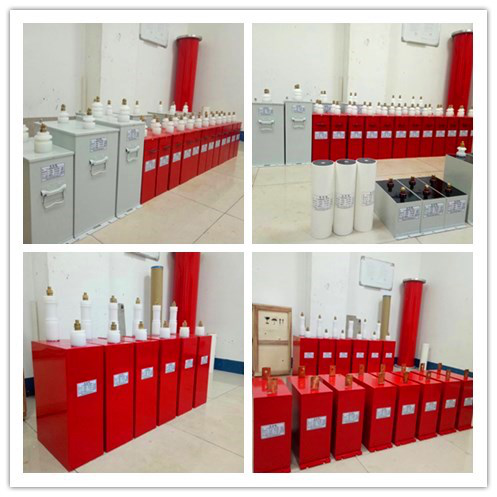
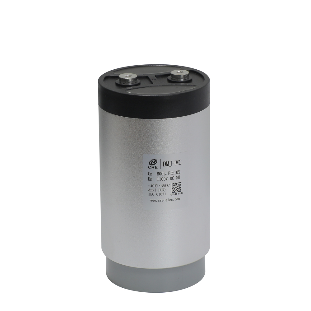
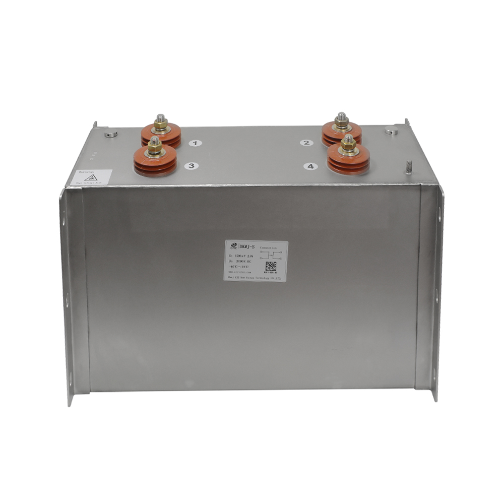
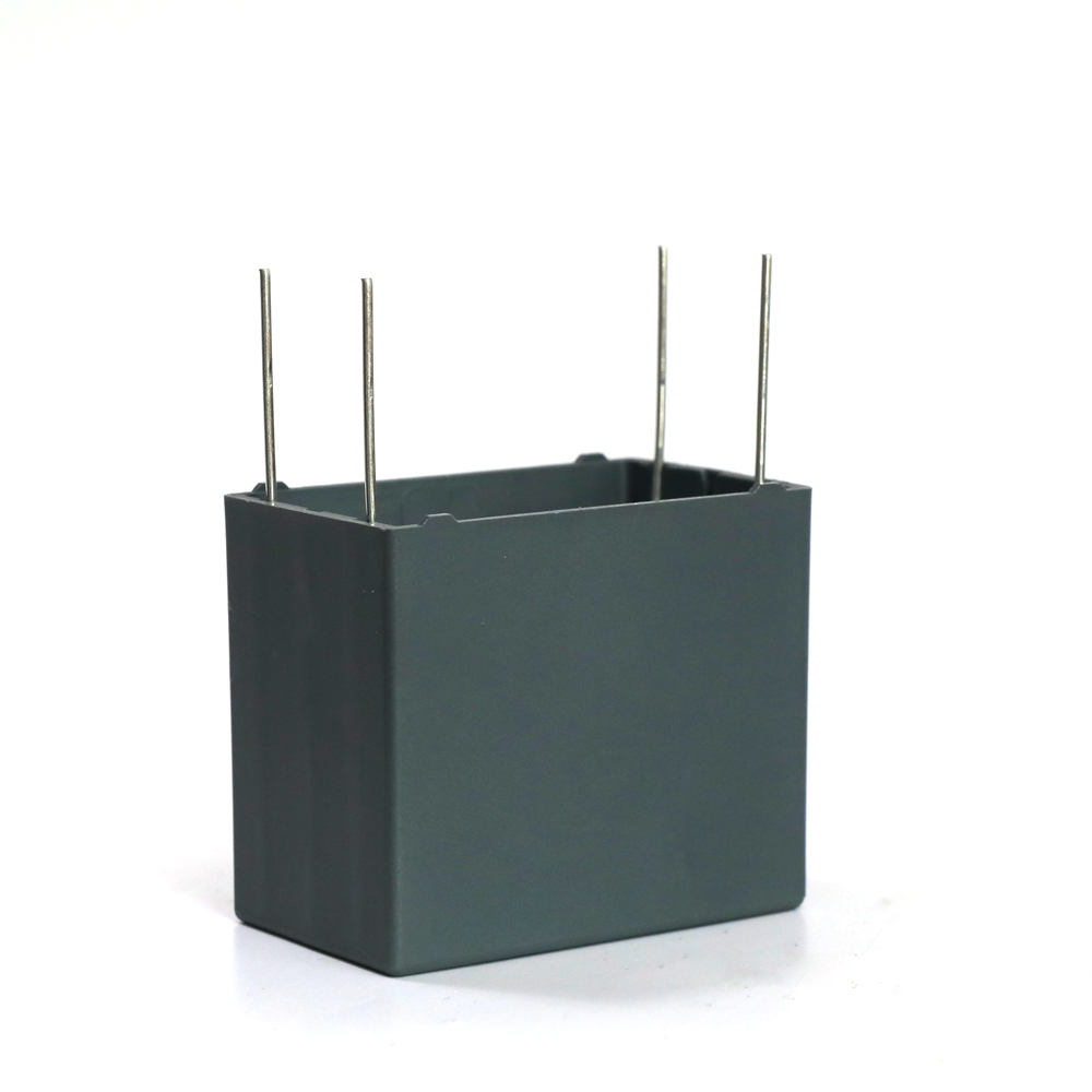
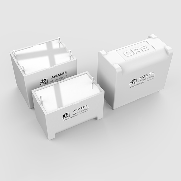
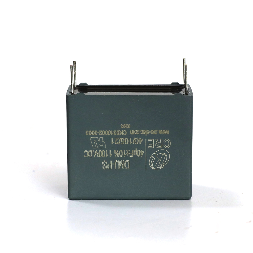
Product detail pictures:
Related Product Guide:
Our business puts emphasis over the administration, the introduction of talented staff, plus the construction of employees building, striving hard to boost the standard and liability consciousness of staff members. Our corporation successfully attained IS9001 Certification and European CE Certification of 2018 New Style Customized Capacitor Bank - Advanced embedded PCB capacitor designed for high power system – CRE , The product will supply to all over the world, such as: Malta, Denmark, Bandung, Based on experienced engineers, all orders for drawing-based or sample-based processing are welcomed. We have now won a good reputation for outstanding customer service among our overseas customers. We will continue to try the best to supply you good quality products and solutions and the best service. We've been looking forward to serving you.
The sales person is professional and responsible, warm and polite, we had a pleasant conversation and no language barriers on communication.