
Special Design for Electronic Capacitor - Advanced embedded PCB capacitor designed for high power system – CRE
Special Design for Electronic Capacitor - Advanced embedded PCB capacitor designed for high power system – CRE Detail:
Technical data
|
Operating temperature range |
Max.Operating temperature.,Top,max: +105℃Upper category temperature: +85℃Lower category temperature: -40℃ |
|
capacitance range |
3~50μF |
|
Rated voltage |
200V.AC~450V.AC |
|
Cap.tol |
±5%(J) ;±10%(K) |
|
Withstand voltage |
2Un DC/10S |
|
Dissipation factor |
tgδ≤0.0015f=1KHz |
|
Insulation resistance |
RS*C≥5000S(at20℃ 100V.DC60S) |
|
Flame retardation |
UL94V-0 |
|
Life expectancy |
100000h(Un; Θhotspot≤70 °C) |
|
Reference standard |
IEC61071; |
|
Operating temperature range |
Max.Operating temperature.,Top,max: +105℃Upper category temperature: +85℃Lower category temperature: -40℃ |
|
capacitance range |
3~50μF |
|
Rated voltage |
200V.AC~450V.AC |
|
Cap.tol |
±5%(J) ;±10%(K) |
|
Withstand voltage |
2Un DC/10S |
|
Dissipation factor |
tgδ≤0.0015f=1KHz |
|
Insulation resistance |
RS*C≥5000S(at20℃ 100V.DC60S) |
|
Flame retardation |
UL94V-0 |
|
Life expectancy |
100000h(Un; Θhotspot≤70 °C) |
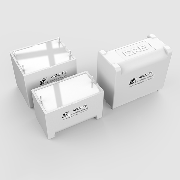
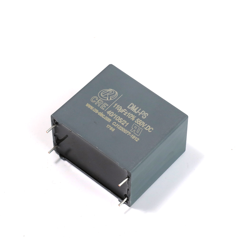
Feature
1. dry film construction;
2. leads with Tinned copper wire;small size.easy installation;
3. low ESL and ESR;
4. High pulse Current.
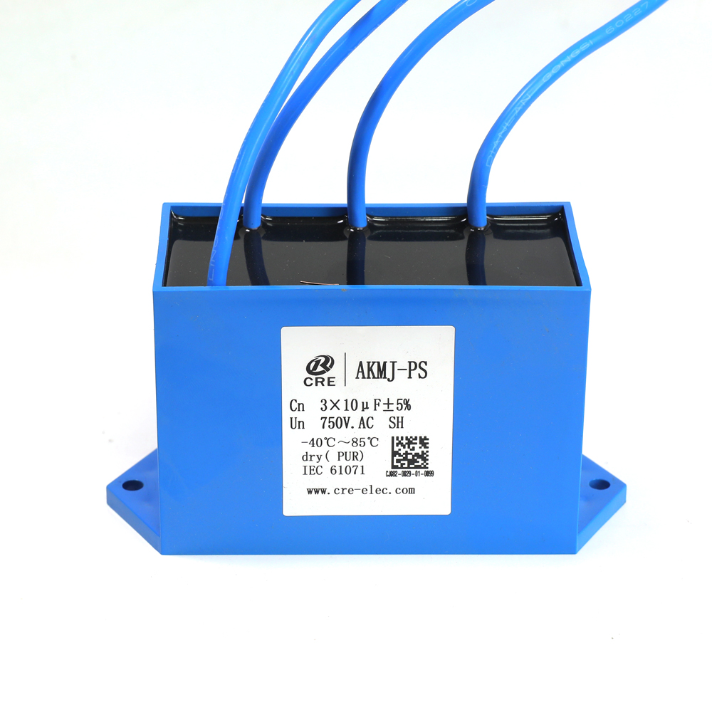
Application
1. Widely used in DC-Link circuit for filtering energy storage;
2. Can replace electrolytic capacitors, better performance and longer life.
3. Pv inverter, wind power converter; all kinds of frequency converter and inverter power supply;
Pure electric and hybrid cars; Charging pile, UPS, Etc.
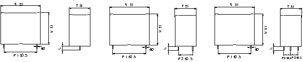
Outline drawing
| (mm) | ||||||||||
| Cn(μF) | L(±1) | T(±1) | H(±1) | φd | P1 | P2 | ESR @10KHz (mΩ) | dv/dt (V/μS) | Ipk(A) | Irms @40℃ @10KHz (A) |
| 20 | 42.5 | 30 | 45 | 1.2 | 37.5 | 2.3 | 30 | 600 | 12 | |
| 20 | 42.5 | 30 | 45 | 1.2 | 37.5 | 20.3 | 1.8 | 30 | 600 | 22 |
| 25 | 57.5 | 30 | 45 | 1.2 | 52.5 | 3.8 | 17 | 425 | 12 | |
| 25 | 57.5 | 30 | 45 | 1.2 | 52.5 | 20.3 | 3.2 | 17 | 425 | 22 |
| 30 | 57.5 | 30 | 45 | 1.2 | 52.5 | 3.5 | 17 | 510 | 12 | |
| 30 | 57.5 | 30 | 45 | 1.2 | 52.5 | 20.3 | 2.9 | 17 | 510 | 22 |
| 30 | 57.5 | 30 | 45 | 1.2 | 52.5 | 10.2 | 2.8 | 17 | 510 | 25 |
| 33 | 57.5 | 35 | 50 | 1.2 | 52.5 | 3.3 | 17 | 561 | 12 | |
| 33 | 57.5 | 35 | 50 | 1.2 | 52.5 | 20.3 | 2.7 | 17 | 561 | 22 |
| 33 | 57.5 | 35 | 50 | 1.2 | 52.5 | 10.2 | 2.6 | 17 | 561 | 28 |
| 35 | 57.5 | 35 | 50 | 1.2 | 52.5 | 3.2 | 17 | 595 | 12 | |
| 35 | 57.5 | 35 | 50 | 1.2 | 52.5 | 20.3 | 2.6 | 17 | 595 | 22 |
| 35 | 57.5 | 35 | 50 | 1.2 | 52.5 | 10.2 | 2.5 | 17 | 595 | 30 |
| 40 | 57.5 | 35 | 50 | 1.2 | 52.5 | 3 | 17 | 680 | 12 | |
| 40 | 57.5 | 35 | 50 | 1.2 | 52.5 | 20.3 | 2.4 | 17 | 680 | 22 |
| 40 | 57.5 | 35 | 50 | 1.2 | 52.5 | 10.2 | 2.3 | 17 | 680 | 30 |
| 45 | 57.5 | 38 | 54 | 1.0 | 52.5 | 2.8 | 17 | 765 | 12 | |
| 45 | 57.5 | 38 | 54 | 1.0 | 52.5 | 20.3 | 2.3 | 17 | 765 | 22 |
| 45 | 57.5 | 38 | 54 | 1.0 | 52.5 | 10.2 | 2.2 | 17 | 765 | 32 |
| 50 | 57.5 | 42.5 | 56 | 1.2 | 52.5 | 2.7 | 17 | 850 | 12 | |
| 50 | 57.5 | 42.5 | 56 | 1.2 | 52.5 | 20.3 | 2.2 | 17 | 850 | 22 |
| 50 | 57.5 | 42.5 | 56 | 1.2 | 52.5 | 10.2 | 2.1 | 17 | 850 | 32 |
| Voltage | Un 400V.DC,Urms250Vac;Us800V | |||||||||
| (mm) | ||||||||||
| Cn(μF) | L(±1) | T(±1) | H(±1) | φd | P1 | P2 | ESR(mΩ) | dv/dt(V/μS) | Ipk(A) | Irms |
| 10 | 42.5 | 33.5 | 35.5 | 1.2 | 37.5 | 2.6 | 40 | 400 | 12 | |
| 10 | 42.5 | 33.5 | 35.5 | 1.2 | 37.5 | 20.3 | 2 | 40 | 400 | 23 |
| 15 | 42.5 | 30 | 45 | 1.2 | 37.5 | 2.3 | 40 | 600 | 28 | |
| 15 | 42.5 | 30 | 45 | 1.2 | 37.5 | 20.3 | 1.8 | 40 | 600 | 28 |
| 15 | 42.5 | 30 | 45 | 1.2 | 37.5 | 10.2 | 1.7 | 40 | 600 | 28 |
| 18 | 42.5 | 33 | 45 | 1.2 | 37.5 | 2.2 | 40 | 720 | 15 | |
| 18 | 42.5 | 33 | 45 | 1.2 | 37.5 | 20.3 | 1.7 | 40 | 720 | 15 |
| 18 | 42.5 | 33 | 45 | 1.2 | 37.5 | 10.2 | 1.6 | 40 | 720 | 15 |
| 20 | 57.5 | 30 | 45 | 1.2 | 52.5 | 3.5 | 20 | 400 | 25 | |
| 20 | 57.5 | 30 | 45 | 1.2 | 52.5 | 20.3 | 2.9 | 20 | 400 | 25 |
| 20 | 57.5 | 30 | 45 | 1.2 | 52.5 | 10.2 | 2.8 | 20 | 400 | 25 |
| 25 | 57.5 | 35 | 50 | 1.2 | 52.5 | 3.4 | 20 | 500 | 28 | |
| 25 | 57.5 | 35 | 50 | 1.2 | 52.5 | 20.3 | 2.8 | 20 | 500 | 28 |
| 25 | 57.5 | 35 | 50 | 1.2 | 52.5 | 10.2 | 2.7 | 20 | 500 | 28 |
| 30 | 57.5 | 38 | 54 | 1.2 | 52.5 | 3.2 | 20 | 600 | 25 | |
| 30 | 57.5 | 38 | 54 | 1.2 | 52.5 | 20.3 | 2.7 | 20 | 600 | 25 |
| 30 | 57.5 | 38 | 54 | 1.2 | 52.5 | 10.2 | 2.6 | 20 | 600 | 25 |
| Voltage | Un 600V.DC,Urms330Vac;Us1200V | |||||||||
| (mm) | ||||||||||
| Cn(μF) | L(±1) | T(±1) | H(±1) | φd | P1 | P2 | ESR(mΩ) | dv/dt(V/μS) | Ipk(A) | Irms |
| 5 | 42.5 | 33.5 | 35.5 | 1.2 | 37.5 | 3.1 | 55 | 275 | 12 | |
| 5 | 42.5 | 33.5 | 35.5 | 1.2 | 37.5 | 20.3 | 2.5 | 55 | 275 | 20 |
| 6.8 | 42.5 | 30 | 45 | 1.2 | 37.5 | 2.8 | 55 | 374 | 12 | |
| 6.8 | 42.5 | 30 | 45 | 1.2 | 37.5 | 20.3 | 2.2 | 55 | 374 | 22 |
| 9 | 42.5 | 30 | 45 | 1.2 | 37.5 | 2.6 | 55 | 495 | 12 | |
| 9 | 42.5 | 30 | 45 | 1.2 | 37.5 | 20.3 | 2.2 | 55 | 495 | 22 |
| 9 | 42.5 | 30 | 45 | 1.2 | 37.5 | 10.2 | 1.9 | 55 | 495 | 28 |
| 10 | 57.5 | 30 | 45 | 1.2 | 52.5 | 4.2 | 30 | 300 | 22 | |
| 10 | 57.5 | 30 | 45 | 1.2 | 52.5 | 20.3 | 3.7 | 30 | 300 | 25 |
| 15 | 57.5 | 35 | 50 | 1.2 | 52.5 | 3.6 | 30 | 450 | 12 | |
| 15 | 57.5 | 35 | 50 | 1.2 | 52.5 | 20.3 | 2.8 | 30 | 450 | 20 |
| 15 | 57.5 | 35 | 50 | 1.2 | 52.5 | 10.2 | 2.7 | 30 | 450 | 28 |
| Voltage | Un 700V.DC,Urms400Vac;Us1400V | |||||||||
| (mm) | ||||||||||
| Cn(μF) | L(±1) | T(±1) | H(±1) | φd | P1 | P2 | ESR(mΩ) | dv/dt(V/μS) | Ipk(A) | Irms |
| 4.7 | 42.5 | 30 | 45 | 1.2 | 37.5 | 3 | 70 | 329 | 12 | |
| 4.7 | 42.5 | 30 | 45 | 1.2 | 37.5 | 20.3 | 2.4 | 70 | 329 | 22 |
| 5 | 42.5 | 30 | 45 | 1.2 | 37.5 | 2.9 | 70 | 350 | 12 | |
| 5 | 42.5 | 30 | 45 | 1.2 | 37.5 | 20.3 | 2.3 | 70 | 350 | 22 |
| 6 | 42.5 | 33 | 45 | 1.2 | 37.5 | 2.8 | 70 | 420 | 12 | |
| 6 | 42.5 | 33 | 45 | 1.2 | 37.5 | 20.3 | 2.2 | 70 | 420 | 22 |
| 8 | 57.5 | 35 | 50 | 1.2 | 52.5 | 4.2 | 40 | 320 | 12 | |
| 8 | 57.5 | 35 | 50 | 1.2 | 52.5 | 20.3 | 3.6 | 40 | 320 | 22 |
| 8 | 57.5 | 35 | 50 | 1.2 | 52.5 | 10.2 | 3.5 | 40 | 320 | 28 |
| 10 | 57.5 | 35 | 50 | 1.2 | 52.5 | 3.9 | 40 | 400 | 12 | |
| 10 | 57.5 | 35 | 50 | 1.2 | 52.5 | 20.3 | 3.3 | 40 | 400 | 22 |
| 10 | 57.5 | 35 | 50 | 1.2 | 52.5 | 10.2 | 3.2 | 40 | 400 | 30 |
| 15 | 57.5 | 38 | 54 | 1.2 | 52.5 | 3.6 | 40 | 600 | 12 | |
| 15 | 57.5 | 38 | 54 | 1.2 | 52.5 | 20.3 | 3.1 | 40 | 600 | 22 |
| 15 | 57.5 | 38 | 54 | 1.2 | 52.5 | 10.2 | 3 | 40 | 600 | 30 |
| Voltage | Un 850V.DC,Urms450Vac;Us1700V | |||||||||
| (mm) | ||||||||||
| Cn(μF) | L(±1) | T(±1) | H(±1) | φd | P1 | P2 | ESR(mΩ) | dv/dt(V/μS) | Ipk(A) | Irms |
| 3 | 42.5 | 30 | 45 | 1.2 | 37.5 | 2.4 | 110 | 330 | 12 | |
| 3 | 42.5 | 30 | 45 | 1.2 | 37.5 | 20.3 | 1.8 | 110 | 330 | 22 |
| 3 | 42.5 | 30 | 45 | 1.2 | 37.5 | 10.2 | 1.7 | 110 | 330 | 25 |
| 3.3 | 42.5 | 30 | 45 | 1.2 | 37.5 | 2.3 | 110 | 363 | 12 | |
| 3.3 | 42.5 | 30 | 45 | 1.2 | 37.5 | 20.3 | 1.7 | 110 | 363 | 22 |
| 3.3 | 42.5 | 30 | 45 | 1.2 | 37.5 | 10.2 | 1.6 | 110 | 363 | 28 |
| 4 | 57.5 | 30 | 45 | 1.2 | 52.5 | 3.1 | 55 | 220 | 12 | |
| 4 | 57.5 | 30 | 45 | 1.2 | 52.5 | 20.3 | 2.5 | 55 | 220 | 22 |
| 4 | 57.5 | 30 | 45 | 1.2 | 52.5 | 10.2 | 2.4 | 55 | 220 | 28 |
| 4.7 | 57.5 | 30 | 45 | 1.2 | 52.5 | 3 | 55 | 258.5 | 12 | |
| 4.7 | 57.5 | 30 | 45 | 1.2 | 52.5 | 20.3 | 2.4 | 55 | 258.5 | 22 |
| 4.7 | 57.5 | 30 | 45 | 1.2 | 52.5 | 10.2 | 2.3 | 55 | 258.5 | 30 |
| 5.6 | 57.5 | 35 | 50 | 1.2 | 52.5 | 2.9 | 55 | 308 | 12 | |
| 5.6 | 57.5 | 35 | 50 | 1.2 | 52.5 | 20.3 | 2.2 | 55 | 308 | 22 |
| 5.6 | 57.5 | 35 | 50 | 1.2 | 52.5 | 10.2 | 2.2 | 55 | 308 | 31 |
| 6 | 57.5 | 35 | 50 | 1.2 | 37.5 | 2.8 | 55 | 330 | 12 | |
| 6 | 57.5 | 35 | 50 | 1.2 | 37.5 | 20.5 | 2.1 | 55 | 330 | 22 |
| 6 | 57.5 | 35 | 50 | 1.2 | 37.5 | 10.2 | 2 | 55 | 330 | 32 |
| 6.8 | 57.5 | 42.5 | 56 | 1.2 | 37.5 | 2.5 | 55 | 374 | 12 | |
| 6.8 | 57.5 | 42.5 | 56 | 1.2 | 37.5 | 20.3 | 1.9 | 55 | 374 | 22 |
| 6.8 | 57.5 | 42.5 | 56 | 1.2 | 37.5 | 10.2 | 1.8 | 55 | 374 | 32 |
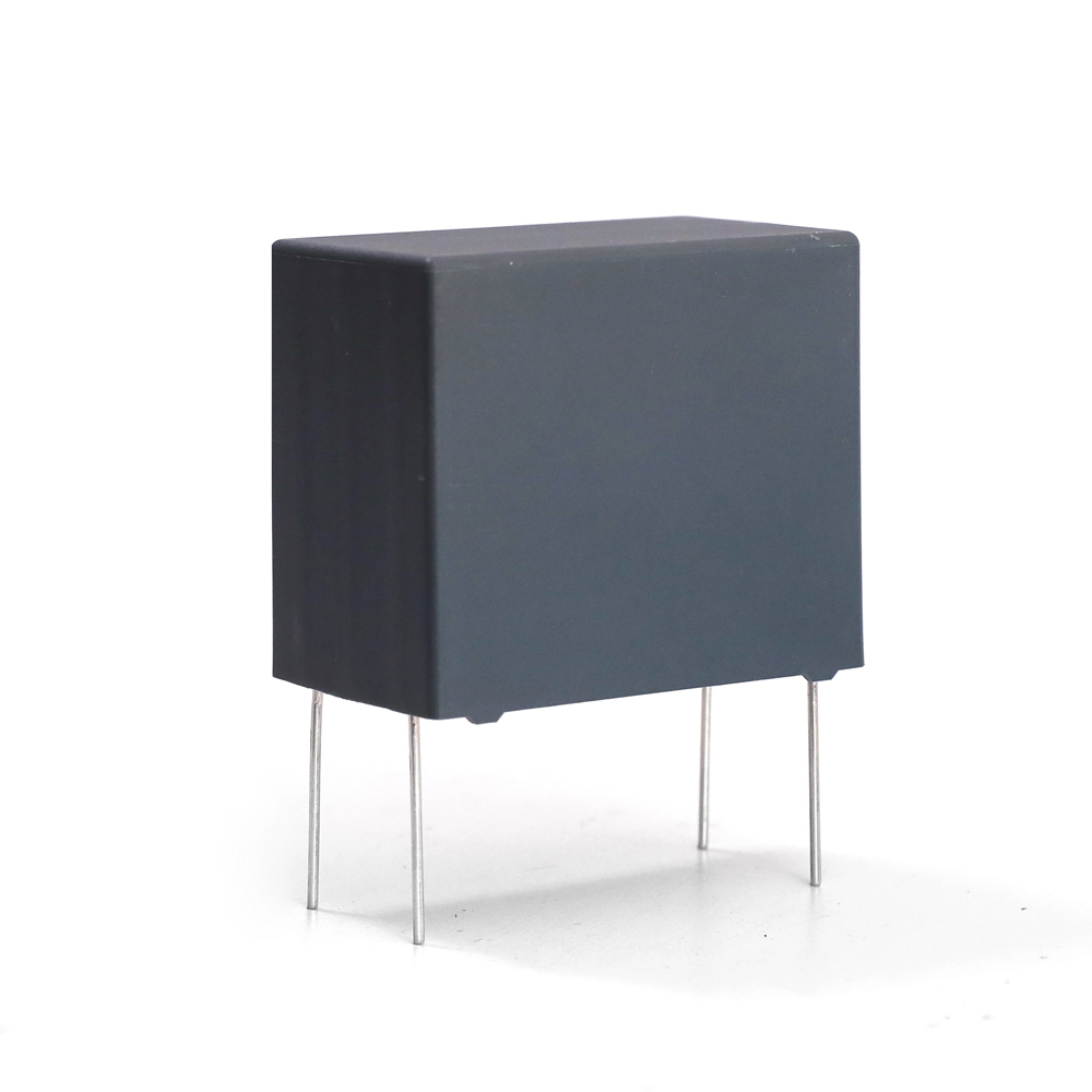
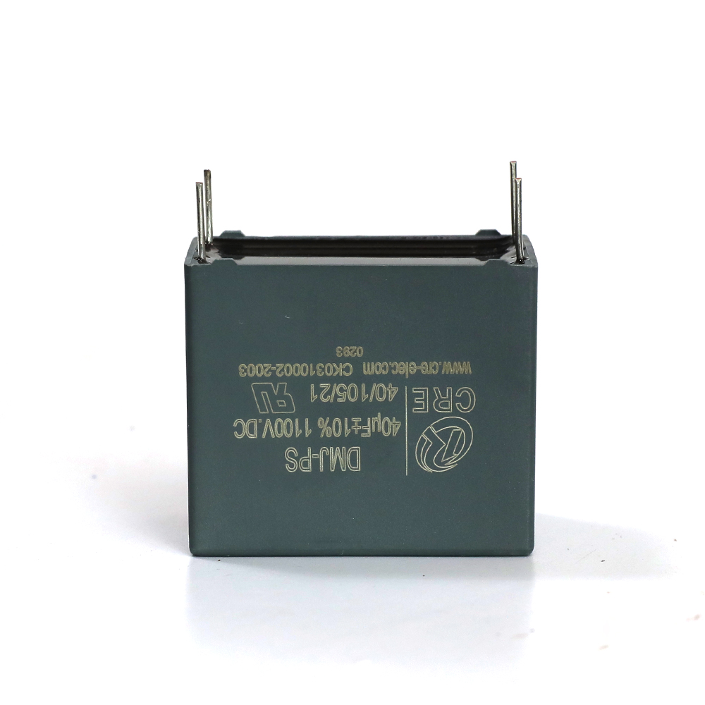
Product detail pictures:
Related Product Guide:
We believe in: Innovation is our soul and spirit. High-quality is our life. Consumer need to have is our God for Special Design for Electronic Capacitor - Advanced embedded PCB capacitor designed for high power system – CRE , The product will supply to all over the world, such as: Poland, Moscow, UK, So We also continuously function. we, focuse on high quality, and are conscious of the importance of environmental protection, most of the merchandise are pollution-free, environmentally friendly solutions, reuse on the solution. We've Updated our catalog, which introduces our organization. n detail and covers the primary products we provide at present, You may also visit our web-site, which involves our most recent product line. We look forward to reactivating our company connection.
The factory technical staff gave us a lot of good advice in the cooperation process, this is very good, we are very grateful.
Send your message to us:
Products categories
-
Manufactur standard Medium Frequency Furnace Re...
-
Popular Design for Metalized Film Capacitor Sol...
-
8 Year Exporter Chinese capacitor manufacturer ...
-
Chinese wholesale Pcb Mounted Film Capacitor -...
-
2018 wholesale price Custom Design Ac Capacitor...
-
Hot sale Ac Filter For Eps Application - High ...


