
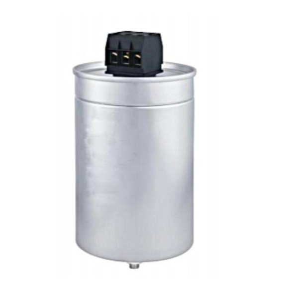
Three Phase AC Filter Film Capacitor with Aluminum Cylindrical Case for Power Equipments
APPLICATIONS
Widely used in power electronic equipment used for the AC filter In the high-power UPS, switching power supply, inverter and other equipment for the AC filter, harmonics and improve power factor control.
TECHNICAL DATA
| Operating temperature range | Max.Operating temperature: +85℃ Upper category temperature : +70℃Lower category temperature : -40℃ |
| Capacitance range | 3*17~3*200μF |
| Rated voltage | 400V.AC~850V.AC |
| Capacitance tolerance | ±5% ( J ) ; ±10% ( K ) |
| Test voltage between terminals | 1.25UN(AC) / 10S or 1.75UN(DC) / 10S |
| Test voltage terminal to case | 3000V.AC / 2S,50/60Hz |
| Over voltage | 1.1Urms ( 30% of on – load – dur. ) |
| 1.15Urms ( 30min / day ) | |
| 1.2Urms ( 5min / day ) | |
| 1.3Urms (1min / day ) | |
| Dissipation factor | Tgδ ≤ 0.002 f = 100Hz |
| Self inductance | <70 nH per mm of lead spacing |
| Insulation resistance | RS×C ≥ 10000S ( at 20℃ 100V.DC ) |
| Withstand strike current | See the specification sheet |
| Irms | See the specification sheet |
| Lifetime expectancy | Useful life time: >100000h at UNDC and 70℃FIT: <10×10-9/h(10 per 109 component h) at 0.5×UNDC,40℃ |
| Dielectric | Metallized polypropylene |
| Construction | Filling with inert gas/ silicone oil, Non-inductive, over-pressure |
| Case | Aluminum case |
| Flame retardation | UL94V-0 |
| Reference standard | IEC61071,UL810 |
SAFETY APPROVALS
|
E496566 |
UL |
UL810, Voltage Limits: Max. 4000VDC, 85℃Certificate No.: E496566 |
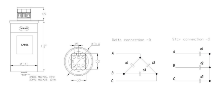
THE CONTOUR MAP
SPECIFICATION TABLE
|
CN (μF) |
ΦD (mm) |
H (mm) |
Imax (A) |
Ip (A) |
Is (A) |
ESR (mΩ) |
Rth(K/W) |
| Urms=400V.AC | |||||||
|
3*17 |
65 |
150 |
20 |
450 |
1350 |
3*1.25 |
6.89 |
|
3*30 |
65 |
175 |
25 |
890 |
2670 |
3*1.39 |
6.25 |
|
3*50 |
76 |
205 |
33 |
1167 |
3501 |
3*1.35 |
4.85 |
|
3*66 |
76 |
240 |
40 |
1336 |
4007 |
3*1.45 |
3.79 |
|
3*166.7 |
116 |
240 |
54 |
1458 |
4374 |
3*0.69 |
3.1 |
|
3*200 |
136 |
240 |
58 |
2657 |
7971 |
3*0.45 |
2.86 |
| Urms=450V.AC | |||||||
|
3*50 |
86 |
205 |
30 |
802 |
2406 |
3*1.35 |
4.36 |
|
3*80 |
86 |
285 |
46 |
1467 |
4401 |
3*1.89 |
3.69 |
|
3*100 |
116 |
210 |
56 |
2040 |
6120 |
3*1.5 |
3.8 |
|
3*135 |
116 |
240 |
58 |
2680 |
8040 |
3*1.6 |
3.1 |
|
3*150 |
136 |
205 |
67 |
3060 |
9180 |
3*2.5 |
3.2 |
|
3*200 |
136 |
240 |
60 |
3730 |
11190 |
3*2 |
3.46 |
| Urms=530V.AC | |||||||
|
3*50 |
86 |
240 |
32 |
916 |
2740 |
3*1.75 |
3.64 |
|
3*66 |
96 |
240 |
44 |
1547 |
4641 |
3*1.36 |
3.32 |
|
3*77 |
106 |
240 |
48 |
1685 |
5055 |
3*1.16 |
3.21 |
|
3*100 |
116 |
240 |
65 |
2000 |
6000 |
3*1.87 |
4.2 |
| Urms=690V.AC | |||||||
|
3*25 |
86 |
240 |
29 |
697 |
2091 |
3*2.22 |
3.54 |
|
3*33.4 |
96 |
240 |
36 |
837 |
2511 |
3*1.81 |
3.21 |
|
3*55.7 |
116 |
240 |
44 |
1395 |
4185 |
3*1.24 |
3.04 |
|
3*75 |
136 |
240 |
53 |
2100 |
6300 |
3*1.31 |
2.87 |
| Urms=850V.AC | |||||||
|
3*25 |
96 |
240 |
30 |
679 |
2037 |
3*1.95 |
3.25 |
|
3*31 |
106 |
240 |
36 |
906 |
2718 |
3*1.57 |
2.98 |
|
3*55.7 |
136 |
240 |
49 |
1721 |
5163 |
3*0.9 |
2.56 |
| Urms=1200V.AC | |||||||
|
3*12 |
116 |
245 |
56 |
1300 |
3900 |
3*3.5 |
3.6 |
|
3*20 |
136 |
245 |
56 |
3300 |
9900 |
3*4 |
2.29 |
Maximum increase of the component temperature (ΔT), resulting from the component’s power dissipation and heat conductivity.
The maximum component temperature-increase ΔT is the difference between the temperature measured on the capacitor’s housing and the ambient temperature (in proximity to the capacitor) when the capacitor is working during normal operation.
During operation ΔT must not exceed 15°C at rated temperature. ΔT corresponds the rise of the component temperature caused by the Irms. In order not to exceed ΔT of 15°C at rated temperature, the Irms must be decreased with an increase of the ambient temperature.
△T = P/G
△T = TC - Tamb
P = Irms2 x ESR = power dissipation (mW)
G = heat conductivity (mW/°C)

